

Process Equipment
The Kavya Pyro Oils Pvt. Ltd., plant comprises of the following
equipment’s:-
-
Plastic / Tire Pyrolysis reactor
-
Hydraulic air lock plastic/ tire feed system
-
The hot air generator
-
The Condensation section
-
Residual carbon receiving and discharge system
-
The cooling system
-
The gas flare system
-
Nitrogen Generation skid mounted plant
-
The flue gas scrubber & chimney

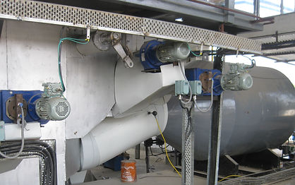
VIEW OF THE KAVYA PYRO OILS PVT. LTD., PLANT, PALEJ, DIST. BHARUCH, GUJARAT

PYROLYSIS REACTOR:- The equipment is designed and fabricate to withstand temperatures upto 800 C. Special grade steel is used for this purpose.
The reactor is stationary. Baled plastic enters the reactor through air lock feeders. Series of paddles move the scrap plastic from front to back inside the reactor. The Hot air from the hot air generator melts the plastic and raises It to pyrolysis temperature of 475 C (Temperature depends on grades of plastic / tire fed) to the reactor.
The Pyro oil vapors emanating from the reactor are cooled in condensers. The liquid so obtained is Pyrolysis oil.
0
0

THE HYDRAULIC AIR Lock feeder receives baled waste plastics or 2” to 3” lumps of waste tires into the feeding chamber.
Sequence-1:- Series of High pressure pistons move in sequence to first compress the material fed into a chamber to form a air tight snug fitting bale.
Sequence-2:- The compressed bale is pushed by the second hydraulic piston through the feed chamber into the reactor.
The sequence of operation continues and during one sequence of operation about 40 kgs of raw material is pushed into the reactor.
Rate of feeding can be varied depending on requirement.
HOT AIR GENERATOR (HAG):- This equipment is fabricated out of stainless steel capable of withstanding temperature of 900 C. The HAG is fired with a dual fuel burner (Oil/Gas). Oil is used during cold start of plant. Once steady state conditions are reached the pyro gas produced during the process is used to fire the boiler and sustain temperatures. The entire process of start up and change over from Oil to Gas is automatic and therefore, the equipment ensures hot air at constant temperature of 750 C to be sent to the reactor.
A FD blower provides the required air to be heated and a certain percentage of flue gas is recycled to ensure full utilization of heat which otherwise would be wasted.
0
0

PYRO VAPOUR CONDENSATION SECTION:- The Pyro vapor emanating from the reactor is at a temperatures above 450 C. The vapours are directed to a series direct and indirect cooling heat exchangers where the vapor is first cooled by cold pyrolysis oil and thereafter by cold water from the cold water ponds.
The liquid so form is Pyrolysis oil and is pumped to the main storage tan through a micrm bag filter to remove all suspended carbon particles..
0


THE COOLING WATER SYSTEM:-
The hot water from the plant heat exchangers and water cooled jackets are directed to cooling towers.
Since cold water is critical for safety and plant operation a standby Cooling tower is also installed to ensure interruption free operation.
The cooled water from cooling towers discharges into the cold water pond from where it is pumped back to the plant for process water for cooling.
FLUE GAS SCRUBBER:-
The scrubber operates on the principle of Venturi scrubbing with water / lime water. Surplus flue gases are passed through the scrubber to remove the harmful components in the flue gas. If presence of Nitric Oxide is detected then the scrubbing is done with Lime solution
COOLING WATER PUMPING STATION & EMERGENCY WATER SUPPLY TANK:-
This installation is vital for trouble free operation of plant.
One pump is in operation for cold water circulation to the plant while the other remains on standby and would be used in case the first pump develops maintenance issues.
The Overhead water tank ensures that in the event of sudden power failure the water flows to the heat exchangers by gravity to ensure that unsafe condition due to overheating do not develop in the plant.
NITROGEN GENERATION SECTION:-
The Plastic/Tire Pyrolysis reactor and other process equipment`s operate under oxygen free conditions.
In fact the entire plant operates under inert atmosphere to avoid self-ignition of the contents at high temperatures.
Therefore, the entire plant before start up is purged with Nitrogen to expel air from the system. Nitrogen is continuously purged at the plastic air lock feeder as well as the residual carbon bin throughout the plant operation.
The packaged PSA Nitrogen plant as shown provides the supply of Nitrogen for purging.
INDUCED DRAFT BLOWER & CHIMNEY:-
The induced draft fam ensures recycling of the flue gas to the reactor and also diverts about 30% of the gas to the scrubber.
Since it operates at high temperatures the blower is made from high temperature resistant stainless steel.
As per statutory regulations the chimney is of diameter 500mm and stands at a height of 30 meters.


OIL WATER SEPERATOR & INTERMEDIATE STORAGE TANKS:-
The oil condensed in heat exchanger also has some condensed moisture which has to separated. This is done in the oil water separator.
Intermediate day storage tanks hold the oil produced before it is filtered and pumped to main storage tank.
This picture shows the oil water separator, associated pumps and the intermediate storage tanks.
RESIDUAL CARBON RECEIVING AND DISCHARGE SYSTEM:-
The residual carbon bin continuously received the residual carbon from the process and is kept in inert atmosphere with Nitrogen purging.
Sensors in the bin alerts the shift engineer when it is full to enable him isolate the bin from the reactor to stop further discharge of carbon till such time the bin contents are cool enough to avoid self ignition, Once cooled the residual carbon is discharged into receptors under atmospheric condition, empty bin is reconnected and carbon discharge restored,